Elevator 
This is the documentation of the project in TTK4145 - Real-time Programming, spring 2020 at NTNU. It is a software for controlling n elevators, working in parallel across m floors. Below you will find the schematic of the modules and the state machine. Additionally, the specification for the project, and how to test the code at home with a elevator-simulator can be found in the sidebar.
Brief system overview
The chosen structure of the system is flat, with no fixed master. A structure where each node acts as a "master" for assigning orders requested locally (from the local button panel) is chosen as opposed to a completely flat structure (with broadcasts and fully global information), in part to better utilize both features of the native Elixir language as well as certain OTP behaviors. We believe this choice has lead to more robust, idiomatic and easily read code.
The order distributor process acts as the decision maker for orders stemming from the local button panel. See OrderDistributor.
The order handler process keeps the list of orders for the local elevator, and is responsible for signalling new orders and clearances to the backup handler and order watchdog. See OrderHandler.
The backup handler process keeps a complete log of all active orders in the system, both local and global. See BackupHandler.
The order watchdog process keeps a list of all active hall orders in the system, with associated watchdog timers in order to redistribute a given order if it has been unhandled for too long. See OrderWatchdog.
The fsm process keeps track of the state of the elevator, responding to triggers in the form of a reached floor to change its state and issue side effects on the order handler. See Fsm.
The output process polls the button sensors and floor sensor of the local elevator, passing messages along when a button has been pressed or a floor has been reached. See Output.
The network process continually broadcasts the node's own identifier and listens for broadcasts from other nodes, as well as signalling to other processes when a new node has been connected to so as to trigger synchronization. See Network.
Below you will find the schematic of the modules and the state machine. Additionally, the specification for the project, and how to test the code at home with an elevator-simulator can be found in the sidebar.
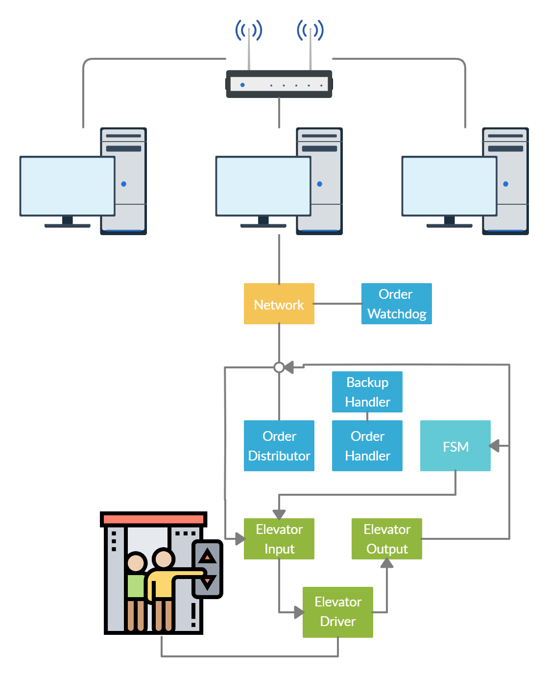
Block Schematic
The processes of the system communicate during regular operation (apart from initialization/reinitialization) as shown in the schematic below.
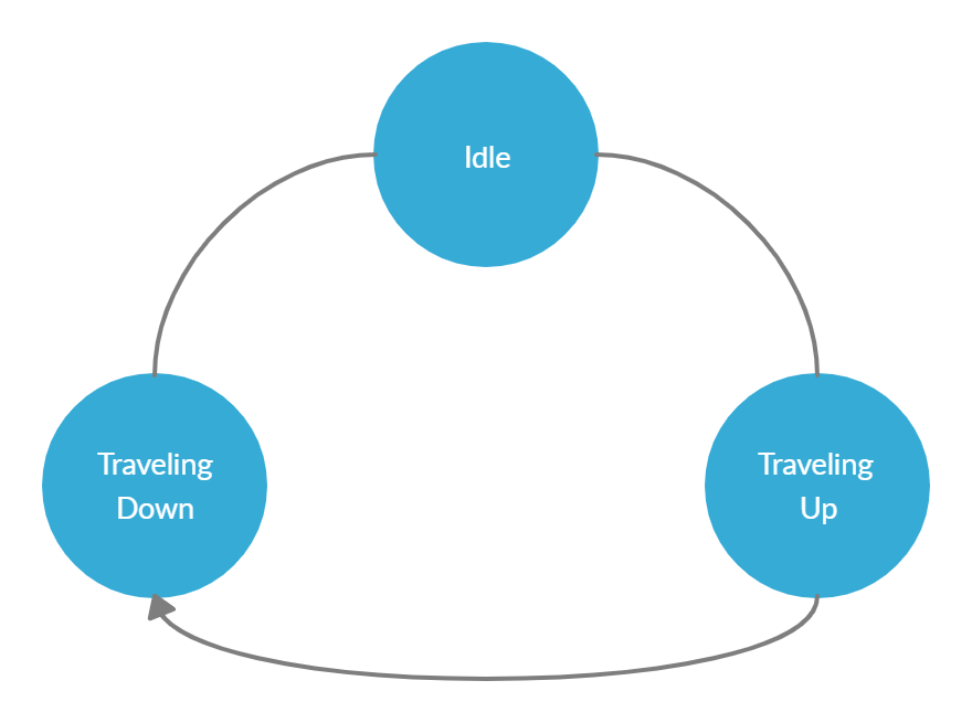
State Machine
A representation of the FSM model used for this project is shown in the image below.
Authors
Student student@stud.ntnu.no
Student student@stud.ntnu.no
Student student@stud.ntnu.no