Setup
A keypad is split into interconnected rows and columns. Typically, you will have a connection for each.
So a 4x4 keypad has 4 row and 4 columns with a totaly of 8 pins required to interact with it. For more specific information,
I'd actually recommend reading over the Parallax 4x4 Membrane Keypad Datasheet
which goes a little more in depth. I'll also be using from images from that datasheet here.
Pin Setup
Wiring the keypad is fairly simple. You'll need to know which pins correspond to the rows and columns and their order. In almost every case, it is like the image below with Row 1 starting on the far left and Column 1 being the wire directly after the last row.
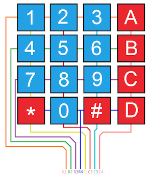
Remember that order matters here. When specifying the :row_pins option for keypad, the first item in the list needs to correspond with the first row on the keypad, i.e. use Keypad, row_pins: [5,6,7] would mean GPIO5 maps to Row 1, GPIO6 maps to Row 2, etc etc.
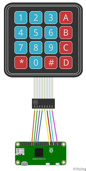
An example pinout connected to a raspberry pi using the default pins would be:
Using External Resistors
COMING SOON
I want to test a bit before I put something out here that might lead people astray and fry boards.
keypad is setting the row pins with the internal PULL_UP resistor. On keypress, that causes the pin to go LOW and it detects that falling edge. If that gets you going to wiring then 👌. Otherwise, check back soon after I've done a little more testing.