The first truly exciting moment in electronics is seeing simple components respond to your own code. Blink an LED, read a button press, and watch your program control the physical world. This section will guide you through the first steps to get there.
If this is your very first time playing with electronics, it's a good idea to go over some basic theory about Voltage, Current, Resistance, and Ohm's Law.
Parts you will need
Here’s a minimal set of parts that you will need to get started:
| Item | Minimum spec | Why you need it | Notes |
|---|---|---|---|
| Raspberry Pi Zero 2(W) (with header pins) | Any 40‑pin Raspberry Pi with headers (Pi 2/3/4/5, or Zero with pre‑soldered header) | Runs your Nerves firmware and exposes GPIO pins | If your board has no header pins, get a pre‑soldered variant or solder a 40‑pin header. |
| Solderless breadboard | Half‑size (or similar) | Quick, tool‑free prototyping | Lets you plug components and wires without soldering. |
| LED (5 mm) | 1–2 pieces, any color | A simple, visible output | The longer leg is the anode (+). Always use a series resistor. |
| Resistors | 220 Ω–330 Ω, 1–2 pieces | Current‑limit for the LED | With 3.3 V GPIO: 330 Ω ≈ 10 mA, 220 Ω ≈ 15 mA. Either is fine for a single LED. |
| Micro Momentary Tactile Button | “Tactile” 6×6 mm or similar | A simple input to read on a GPIO | Use internal pull‑ups/pull‑downs in software, or add a 10 kΩ resistor if you prefer a physical pull. |
| Dupont jumper wires | 10–20 mixed | Connects the Pi to the breadboard | Use female‑to‑male for Pi‑to‑breadboard, plus a few male‑to‑male for breadboard jumpers. |
You’ll also need the usual Raspberry Pi parts (a good power supply and a microSD card flashed with your Nerves firmware).
Elixir Circuits
Elixir Circuits provides different interfaces to communicate with hardware devices connected to your target.
There is a quickstart guide you can follow to get started in no time.
Circuits GPIO has great documentation if you want to use your own firmware and not use Livebook.
As mentioned in the Example projects section, you can find several examples on how to get started with hardware projects such as:
- Blinky, showing you how to blink the onboard LED.
- Hello GPIO, which will use an LED connected to a GPIO pin, and a manual switch on another pin.
These two examples are great ways to get started with electronics on Nerves.
Control your first components
The goal is to safely connect one LED (output) and one push button (input) to your Raspberry Pi’s 40‑pin header so you can control them from Elixir.
The absolute basics
- GPIO pins on Raspberry Pis are 3.3 V only. Don’t connect them to a 5 V source or you risk damaging them.
- LEDs are directional. The longer leg is called the anode "+". The shorter leg goes to ground (GND).
- Always add a series resistor (220–330 Ω) with an LED to limit current. This helps ensure you don't damage the LED.
- Buttons are not directional. You’ll connect one side to a GPIO and the other to GND and then enable a built‑in "pull‑up" in software.
What does "pull-up" / "pull-down" mean?
Digital inputs need a known default value. A pin that isn’t connected to anything can "float" (randomly read 0 or 1). A pull-up or pull-down ties the pin to a stable level so it only changes when your circuit intentionally drives it. It makes its value "predictable".
- Pull-up: an internal resistor connects the pin to 3.3 V. The pin reads 1 (HIGH) unless you press the button to connect it to GND (0).
- Pull-down: an internal resistor connects the pin to GND. The pin reads 0 (LOW) unless you press the button to connect it to 3.3 V (1).
In software with Circuits.GPIO you choose the mode when opening the pin:
# Use a pull-up (button to GND):
{:ok, btn} = Circuits.GPIO.open(27, :input, pull_mode: :pullup)

# Or use a pull-down (button to 3.3V):
{:ok, btn} = Circuits.GPIO.open(27, :input, pull_mode: :pulldown)
Hardware alternative: you can add your own external resistor (e.g., 10 kΩ) instead of using the internal one. Beginners usually start with the internal version because it’s simpler.
Recommended pins on a Raspberry Pi
To keep things consistent with common examples:
- LED output: GPIO 17 (aka BCM/GPIO 17, physical pin 11)
- Button input: GPIO 27 (aka BCM/GPIO 27, physical pin 13)
- Ground: any GND pin (e.g., physical pin 9)
- 3.3 V power: physical pin 1 (for other circuits; not needed for the LED with the wiring below)
If you’re unsure about pin names vs. physical locations, see the Raspberry Pi pinout. "BCM/GPIO" numbers are what you’ll use in software.
Wire the LED (output)
- Put the LED on the breadboard. Note the long leg (anode, +) and short leg (cathode, −).
- Connect a resistor (220–330 Ω) from the long leg to a row on the breadboard.
- Use a female‑to‑male jumper to connect that resistor’s other end to the Pi’s physical pin 11 (BCM/GPIO 17).
- Connect the LED’s short leg to GND (e.g., physical pin 9) using another jumper.
- Now start your pi and connect to it via ssh.
- In IEx, you can now run the following commands to light up your LED!
# We set GPIO 17 as output pin
{:ok, led} = Circuits.GPIO.open("GPIO17", :output)
# We set it to high, so 3.3V
Circuits.GPIO.write(led, 1)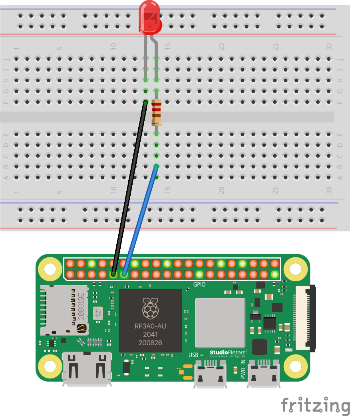
This makes the LED turn on when GPIO 17 is set HIGH (3.3 V) and off when set LOW (0 V).
For a concrete example using this in an actual firmware, you can check the Hello GPIO example on github.
Wire the button (input)
- Place a 6×6 mm tactile button so it straddles the breadboard gap (so its two sides aren’t already connected).
- Connect one leg of the button to the Pi’s physical pin 13 (BCM/GPIO 27).
- Connect the opposite leg of the button to GND (e.g., physical pin 9).
- Now start your pi and connect to is via ssh.
- In IEx, you can run the following code to see how the button behaves!
# We set GPIO 27 as input, with the internal pullup resistor
{:ok, btn} = Circuits.GPIO.open("GPIO27", :input, pull_mode: :pullup)
Circuits.GPIO.read(btn)
# Run this while holding the button pressed or released to see change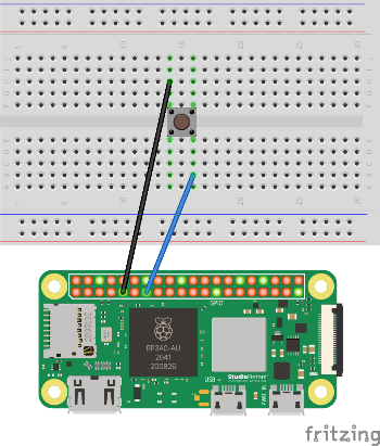
For a concrete example using this in an actual firmware, you can check the Hello GPIO example on github.
Common mistakes
- The LED is wired backwards → swap the LED orientation (long leg toward the resistor/GPIO).
- There is no resistor → add a 220–330 Ω resistor in series with the LED.
- Wrong pin numbers → double‑check BCM/GPIO vs. physical pins.
- The button reads the same value always → ensure one side goes to the GPIO pin, the other to GND, and that
pull_mode: :pullupis set in your software.