
![]()
This is the base Nerves System configuration for the MangoPi MQ Pro.
The MangoPi MQ Pro works well, but there are active updates upstream and here. Backwards incompatible changes may be out of our control.
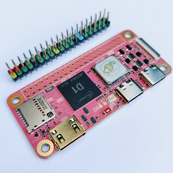
<sup>[Image credit](#mangopi)</sup>
| Feature | Description |
|---|---|
| CPU | 1 GHz 64 bit RISC-V |
| Memory | 512 MB or 1 GB DRAM |
| Storage | MicroSD |
| Linux kernel | 6.1 w/ patches |
| IEx terminal | UART ttyS0 |
| GPIO, I2C, SPI | Yes - Elixir Circuits |
| Display | Yes, but not supported yet |
| ADC | No |
| PWM | 8 channels (4 exposed), but no Elixir support |
| UART | ttyS0 |
| Camera | Yes, but not supported yet |
| Ethernet | No |
| WiFi | Onboard WiFi |
| RTC | No |
| HW Watchdog | Yes |
Using
The most common way of using this Nerves System is create a project with mix nerves.new and add mangopi_mq_pro references where needed and in a similar way
to the default systems like bbb, etc. Then export MIX_TARGET=mangopi_mq_pro.
See the Getting started
guide
for more information.
If you need custom modifications to this system for your device, clone this repository and update as described in Making custom systems.
Example use
This example assumes some familiarity with Nerves. To use this system, you'll need OTP 25. Follow the Nerves installation instructions for additional system dependencies.
Creating a new hello world application:
mix nerves.new hello_mango
cd hello_mango
Open up your mix.exs and add :mangopi_mq_pro to the @all_targets list at
the top. It's ok to delete targets that you don't plan on using.
Then add the :nerves_system_mango_mq_pro dependency to the deps function:
{:nerves_system_mangopi_mq_pro, "~> 0.1", runtime: false, targets: :mangopi_mq_pro},This will load the latest released version. To use the latest code on the main
branch here, add the following line:
{:nerves_system_mangopi_mq_pro, runtime: false, targets: :mangopi_mq_pro, nerves: [compile: true], git: "https://github.com/nerves-project/nerves_system_mangopi_mq_pro", branch: "main"}To build and write to a MicroSD card, run:
export MIX_TARGET=mangopi_mq_pro
mix deps.get
mix firmware
mix burn
Console access
The console is configured to output to the UART on pins 8 and 10 on the 40-pin GPIO connector. This is just like the Raspberry Pi. A 3.3V FTDI cable is needed to access the output.
Networking
The board has two network interfaces, a WiFi module and a virtual Ethernet on the USB C connector marked "OTG". If virtual Ethernet isn't working for you, try a different USB cable. You're welcome.
GPIO
The following table is a mapping between the logical GPIO numbers used in software (sysfs, Circuits.GPIO), and the pin numbers on the 20x2 Raspberry Pi header. For example, to control pin 11 you would open a connection to GPIO 117.
{:ok, pin} = Circuits.GPIO.open(117, :output)The comments in the "Note" columns come from the official schematic.
| GPIO | Note | Pin | Pin | Note | GPIO |
|---|---|---|---|---|---|
| 3v3 | 1 | 2 | Vin | ||
| 205 | SDA | 3 | 4 | Vin | |
| 204 | SCL | 5 | 6 | GND | |
| 39 | MCLK | 7 | 8 | TX0 | 40 |
| GND | 9 | 10 | RX0 | 41 | |
| 117 | TX1 | 11 | 12 | I2S_CLK / PWM0 / Audio | 37 |
| 118 | RX1 | 13 | 14 | GND | |
| 32 | PWM3 | 15 | 16 | PWM4 | 33 |
| 3v3 | 17 | 18 | DC | 110 | |
| MOSI | 19 | 20 | GND | ||
| MISO | 21 | 22 | RX2 | 65 | |
| SCLK | 23 | 24 | CS0 | ||
| GND | 25 | 26 | CS1 | 111 | |
| 145 | SDA | 27 | 28 | SCL | 144 |
| 42 | 29 | 30 | GND | ||
| 43 | 31 | 32 | TX2 | 64 | |
| 44 | 33 | 34 | GND | ||
| 38 | PWM1 / I2S_FS | 35 | 36 | DI2 | 34 |
| 113 | 37 | 38 | I2S_DI0 | 35 | |
| GND | 39 | 40 | I2S_D0 | 36 |
You can also get the pinout at the IEx prompt by using the pinout library.
Pinout diagram

Schematics and datasheets
- Schematics
- IBOM - Interactive web page to help you find what part is located where
- D1 user manual (PDF, 1390 pages)
Thanks
The most helpful Allwinner D1 information comes from linux-sunxi.org/Allwinner_Nezha. All of the work here wouldn't have been possible with out it. Thanks especially to smaeul's Allwinner D1 Linux fork
Here are more useful links:
Image credit: This image is from mangopi.cc.